Remote Operations
Links/addresses:
- HET 5min weather averages: hetwx
- Dome audio stream: streaming in VLC on Juno will give lowest latency, but it is also available anywhere on the VPN with the xstream link below:
vlc rtp://@:4445 --sout-rtp-caching 40 &
vlc http://192.168.66.45/xstream &
- NEW Dome audio stream, now with higher fidelity:
vlc rtp://@:4446 --sout-rtp-caching 40 &
vlc http://192.168.66.37/xstream &
- Streaming video from video switch:
vlc http://guider:iamTO@192.168.66.87/mjpg/video.mjpg &
- CCAS shutter remote control: http://10.10.10.22/
Note that as of 12 Sep 2020, the status of the shutter is being correctly displayed, both on the web interface and on the rack in the control room (thanks to Herman for fixing that!).
- Louver remote control: http://192.168.66.59/
All louvers are controlled at the same time: 0 deg is closed, 90 deg is full open (sensor on louver 13)
Clicking "Open fully" or "Close fully" will result in a 25s pulse (interlocked), can "Stop" if needed
Clicking on "Open 10deg" or "Close 10deg" will give a short pulse to open that much
Louver enclosure has Local/Remote switch at bottom right - must be set to "Remote" for this interface to work
- Jove IP address: 192.168.66.17
- Largely not in use as we transition fully to Juno
- Can use VNC viewer to access:
- 5902: tiny display, kde
- 5903: 2560x1080 kde (Justen using this)
- 5904: 1920x1080 kde (Nathan using this)
- 5905: 2560x1440 kde (Amy using this)
- 5906: 2560x1440 kde (Cassie using this)
- Can start/stop VNC servers with:
guider@jove:~$  vncserver -kill :9
guider@jove:~$  vncserver :9 -geometry 2560x1440
- Juno IP address: 192.168.66.26
- We use NoMachine on Juno, some documentation here
- Chris' Google document contains more details about Juno and NoMachine
- Juno NoMachine web-based access:
http://192.168.66.26:4080
http://juno.as.utexas.edu:4080 (if name resolution is working)
- VPN access:
- We are using a "Virtual Private Network" (VPN) to access the internal HET network: with l2tp 206.76.137.14 preshare
Adobe:
| Humidity % | 0.3µ dust | 1.0µ dust |
|---|---|---|
| 25 | 2,800,000 | 100,000 |
| 26 | 2,891,414 | 98,571 |
| 27 | 2,982,842 | 97,142 |
| 28 | 3,074,270 | 95,713 |
| 29 | 3,165,698 | 94,284 |
| 30 | 3,257,126 | 92,855 |
| 31 | 3,348,554 | 91,426 |
| 32 | 3,439,982 | 89,997 |
| 33 | 3,531,410 | 88,568 |
| 34 | 3,622,838 | 87,139 |
| 35 | 3,714,266 | 85,710 |
| 36 | 3,805,694 | 84,281 |
| 37 | 3,897,122 | 82,852 |
| 38 | 3,988,550 | 81,423 |
| 39 | 4,079,978 | 79,994 |
| 40 | 4,171,406 | 78,565 |
| 41 | 4,262,834 | 77,136 |
| 42 | 4,354,262 | 75,707 |
| 43 | 4,445,690 | 74,278 |
| 44 | 4,537,118 | 72,849 |
| 45 | 4,628,546 | 71,420 |
| 46 | 4,719,974 | 69,991 |
| 47 | 4,811,402 | 68,562 |
| 48 | 4,902,830 | 67,133 |
| 49 | 4,994,258 | 65,704 |
| 50 | 5,085,686 | 64,275 |
| 51 | 5,177,114 | 62,846 |
| 52 | 5,268,542 | 61,417 |
| 53 | 5,359,970 | 59,988 |
| 54 | 5,451,398 | 58,559 |
| 55 | 5,542,826 | 57,130 |
| 56 | 5,634,254 | 55,701 |
| 57 | 5,725,682 | 54,272 |
| 58 | 5,817,110 | 52,843 |
| 59 | 5,908,538 | 51,414 |
| 60 | 6,000,000 | 49,985 |
Remote E-stop quick-start guide:
Quick Start Manual, Remote Networked Estop System for HET
March 25, 2021 George Damm
Overview In the event that a TO must operate the HET from home, this manual serves as a guide to set up the Remote Networked EStop System and make it operational. Details of the system are defined in other HET documents:
- Remote Networked Estop Setup in housing describes how to physically setup the equipment in a house.
- Remote Networked Estop System Overview describes how the system interconnects at a network level and how variables are shared across the various PLCs in the system.
- Remote Networked Estop Operating Manual describes the details of the hardware and software and how the system operates at the user level.
1. Hardware/Software Preparation
- Make sure that your Remote Unit is plugged into power and internet. This unit should also be located such that the EMO button is readily accessible in the event of a problem and the indicator LEDs are visible.
- Connect to the HET VPN or by other means to the HET private network.
- Open the web server on your Remote unit. On your browser, this is located at Amy:206.76.138.27:2000, Cassie:206.76.138.28:2000, Justen:206.76.138.13:200.
- Open the web server for the Central unit in the Room. Within the HET private network, on your browser, the Central unit is located at 192.168.66.72:2000
- Make sure that the Central Unit’s Run/Test GUI indicator is green, in the ‘Run’ mode
- Ensure that the EMO button on the Remote unit is not pressed down. If it is, rotate the button until it pops back up.
2. Setup Communications and Control
- Determine if your Communications LED and GUI indicator are Green. If not, do the following
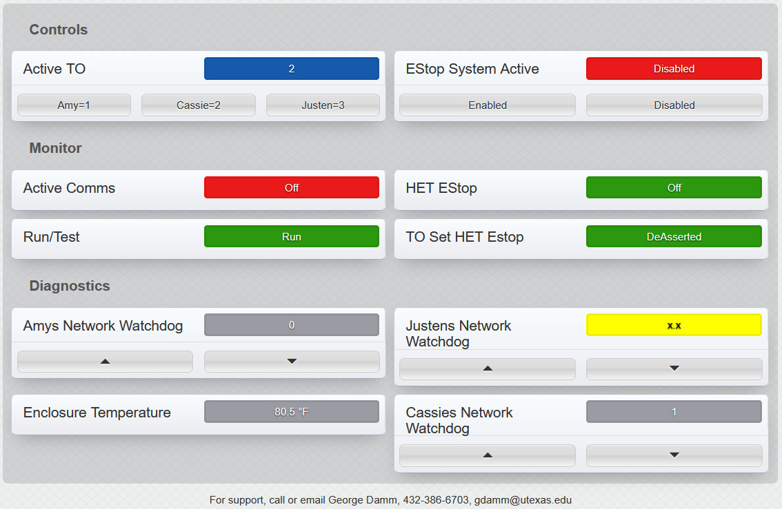
- Check the Central Unit GUI. In the ‘Diagnostics’ section (the lowest 4 indicators), observe the state of your colored indicator labeled ‘(Amys)(Justens)(Casssies) Network Watchdog’ as shown in Figure 1 below. If the colored indicator is yellow with an x.x in its box, as shown in Justens Network Watchdog, then there is a network connectivity problem between the Central and Remote Units. If this cannot be quickly solved, call George Damm or Stephen Cook. Ideally, there will be a grey box with either a 1 or 0 showing, as is shown for Amy’s and Cassie’s watchdog in Figure 1.
- Most likely the network watchdog for your unit needs to be restarted. This is a bug that Xytronix is aware of but for the time being, does not have a fix. The network watchdog toggles between a 0 and 1. To restart it, use the up or down button below this number to force the watchdog to its other state. Typically, this will restart the watchdog. When this happens, the watchdog will switch back and forth between 0 and 1 and the Communications LED on your Remote unit and the GUI indicator will turn green. If the watchdog does not restart, call George Damm or Stephen Cook.
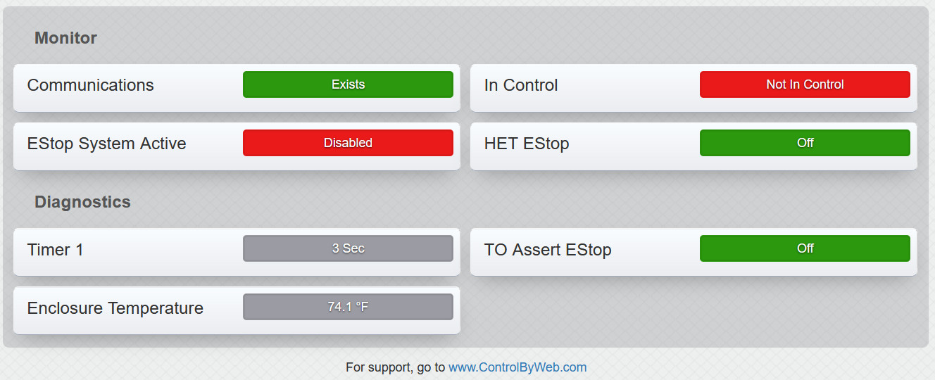
- You can verify the proper operation of the watchdog timer by looking at your own Remote Unit GUI, as shown in Figure 2 below. The Watchdog Timer should show a continually reset count down from 6 seconds. If ever this count down timer remains static, then the watchdog timer has failed.

Figure 1. Screenshot of the Central Unit GUI

Figure 2. Screen shot of the Remote Unit GUI
3. Take control of the system.
- If the system recognized that you are in control, the ‘In Control’ LED and GUI indicator at the Remote unit, should be green. If not, observe the state of the ‘Active TO’ indicator in the Central Unit GUI as shown in Figure 1, and do the following:
- If it does not indicate that you are the Active TO, then press the button below the indicator to select yourself as the Active TO. If this does not cause the ‘In Control’ LED and GUI indicator to turn green, then call George Damm or Stephen Cook. When these indicators turn green, observe the Central Unit GUI and that the ‘Active Comms’ indicator is also green.
- If you are presently designated as that Active TO, but your Remote Unit ‘In Control LED is red, then select any other TO’s to become active, wait several seconds and then once again select yourself as the active TO. If this does not cause the ‘In Control’ LED and GUI indicator to turn green, then call George Damm or Stephen Cook. When these indicators turn green, observe the Central Unit GUI and that the ‘Active Comms’ indicator is also green. This indicator is shown in Figure 1.
4. Enable the System
- By default, the Remote Networked Estop System should be left in the Disabled State. This is indicated in the Central Unit and each of the Remote Unit’s GUI. The Estop System Active indicator should be red. Each of the Remote and Central Unit Enclosures will also show red for the Estop Active LED. This condition ensures that these Remote Units will not unintentionally cause an Estop to be asserted.
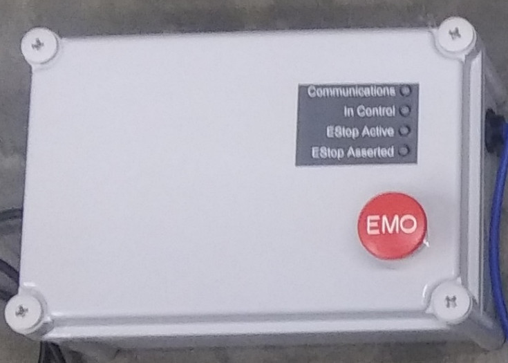
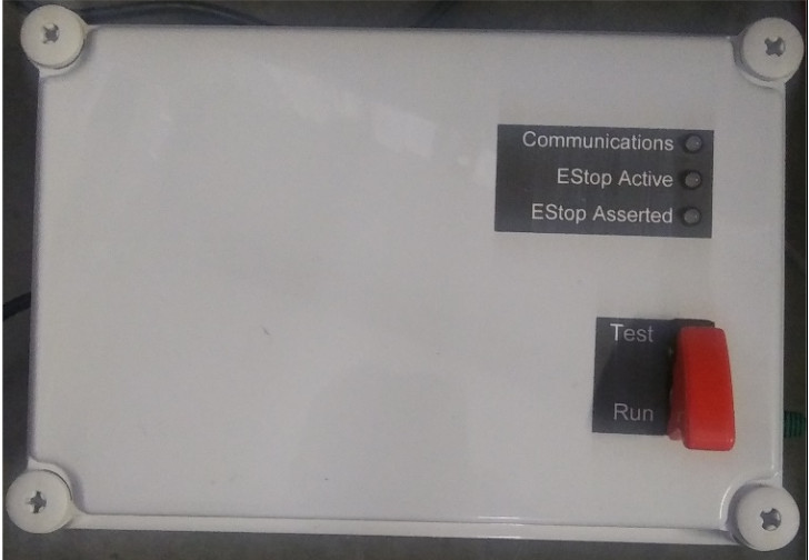
- To enable the system to accept an Estop, in the Central Unit GUI, press the Enable button in the ‘Estop System Active Display. The indicator in this section should change from red to green as should this same display in all TO Remote Unit GUI and as should the Estop Active LEDs on all of the Remote and Central units. If the indicator does not change as expected, then call George Damm Figure 3 below is a photo of the Remote units. Figure 4 below is a photo of the Central unit.
- After use, be sure to return the state, Estop System Active, back to Disabled.

Figure 3. Photograph of a Remote unit showing the user interface, 4 LEDs, 1 pushbutton.

Figure 4. Photograph of the Central unit, showing 3 indicator LEDs, 1 toggle switch.
5. Test the Estop Using Test Mode, This will not activate the HET EStop
- In order to test the operation of the Remote Networked Estop System, place the Run/Test? toggle switch on the Central unit into the Test position.
- When a Remote unit EMO button is pressed, it will appear that an HET Estop has been asserted. While the toggle switch is in the Test position, no Estop can be actuated by the Remote Networked Estop System.
- When finished testing,
- Release the Estop, rotate the EMO button until it pops back up.
- Place the Run/Test toggle switch back into the Run position
6. Activate an HET Estop
- Make sure that the Run/Test toggle switch on the Central unit is in the Run position.
- To activate an Estop, simply press the EMO button on the Remote unit.
- This action is verified by observing the ‘Estop Asserted’ LED on the Remote unit turning red and the ‘HET Estop’ indicator on the Remote unit GUI also turning red. This indication is feedback from the HET hardwired Estop system. This indicator will show an asserted Estop, regardless of initiation, local or remote.
- To release an Estop, rotate the EMO button until it pops back up.
7. Typical Scenarios for Remote Enclosure Indicators, Reference only, Not required for testing

- Remote Unit is communicating with Central Unit, is Actively in Control, the Estop system is active and there is no HET Estops. This is the ideal scenario for a TO during nights ops, working from home.

- Remote Unit is communicating with Central Unit, is Actively in Control, the Estop system is active. Estop is asserted at HET either from this Remote Unit or from a button at HET.

- Remote Unit is Communicating with the Central Unit, it is not in Control, the Estop system is Active and there are no HET Estops

- Remote Unit is Communicating with the Central Unit, it is not in Control, the Estop system is not Active and there are no HET Estops
Last modified 20 months ago
Last modified on Sep 23, 2022 7:03:51 PM
Attachments (8)
- fig1.jpg (161.1 KB) - added by stevenj 23 months ago.
- fig2.jpg (125.4 KB) - added by stevenj 23 months ago.
- fig3.jpg (54.7 KB) - added by stevenj 23 months ago.
- fig4.jpg (48.2 KB) - added by stevenj 23 months ago.
- figa.jpg (12.5 KB) - added by stevenj 23 months ago.
- figb.jpg (12.9 KB) - added by stevenj 23 months ago.
- figc.jpg (13.0 KB) - added by stevenj 23 months ago.
- figd.jpg (13.3 KB) - added by stevenj 23 months ago.
Download all attachments as: .zip